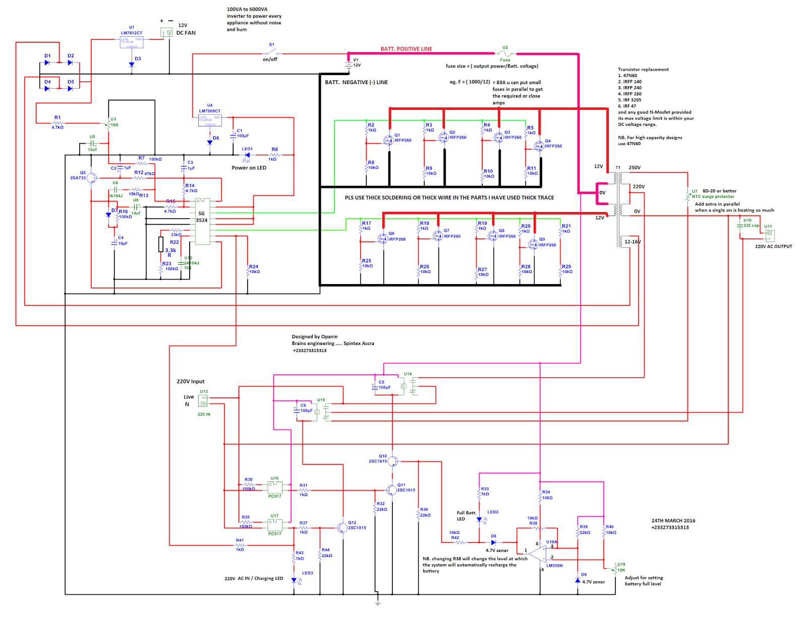
48 Volt Inverter Circuit Diagram
Thirty years ago we created this circuit very difficult.
48 volt inverter circuit diagram. This is inverter circuit 500w output. It will convert 12vdc to 220v 50hz. You can build it easily and inexpensive. Because like working outdoors or to backup storage to use when necessary.
Simple low power inverter circuit 12v dc to 230v or 110v ac diagram using cd4047 and irfz44 power mosfet gallery of electronic circuits and projects providing lot of diy circuit diagrams robotics microcontroller projects electronic development tools. Principle behind this circuit. The basic idea behind every inverter circuit is to produce oscillations using the given dc and apply these oscillations across the primary of the transformer by amplifying the current. Simple pwm inverter circuit diagram using pwm chip sg3524 gallery of electronic circuits and projects providing lot of diy circuit diagrams robotics microcontroller projects electronic development tools.
The post discuses the how to make a 3 phase inverter circuit which can be used in conjunction with any ordinary single phase square wave inverter circuit. Using two switch topology. When developing a welding inverter i applied forward inverter with two switches topology. Here the input line voltage traverses through the emi filter further smoothing with big capacity.
Lets build an icl7107 digital voltmeter circuit. It is an important basis for other measurement tools circuits.


