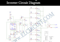
Irfz44n Inverter Circuits
This tutorial is written primarily for non academic hobbyists so i will try to simplify the concept and focus more on the practical side of things.
Irfz44n inverter circuits. 555 timer ic inverter circuit schematic 12v to 220v gallery of electronic circuits and projects providing lot of diy circuit diagrams robotics microcontroller projects electronic development tools. Hi its my first time build an inverter neh thing is the circuit diagram of the pwm doesnt seem to make sense as it shows the ic with all sided pins while the one at the bottom and the one i bought is two sided and also it doesnt say as to the porality of the ic or where the lines to the mosfets come from. Could you please grant me. In this post we learn 2 easy to build induction heater circuits which work with high frequency magnetic induction principles for generating substantial magnitude of heat over a small specified radius.
The discussed induction cooker circuits are truly simple and uses just a few active and passive ordinary components for the required actions. Using the high low side driver ir2110 explanation and plenty of example circuits. Pwm is used in all sorts of power control and converter circuits. Some common examples include motor control dc dc converters dc ac inverters and lamp dimmers.
Electronic projects mostly associated with solar power. With these requirements in mind and some others i decided on a variation of national semiconductors micro wiretm. Lets talk about the basics of mosfet and how to use them.


