Logic Inverter Circuit
Logic not gate tutorial.
![]()
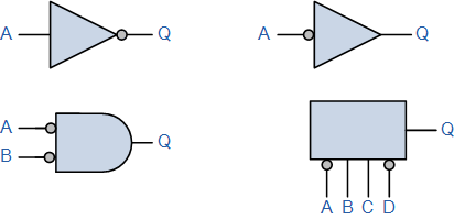
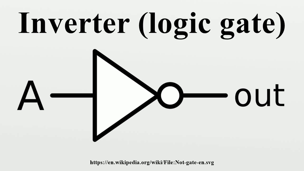
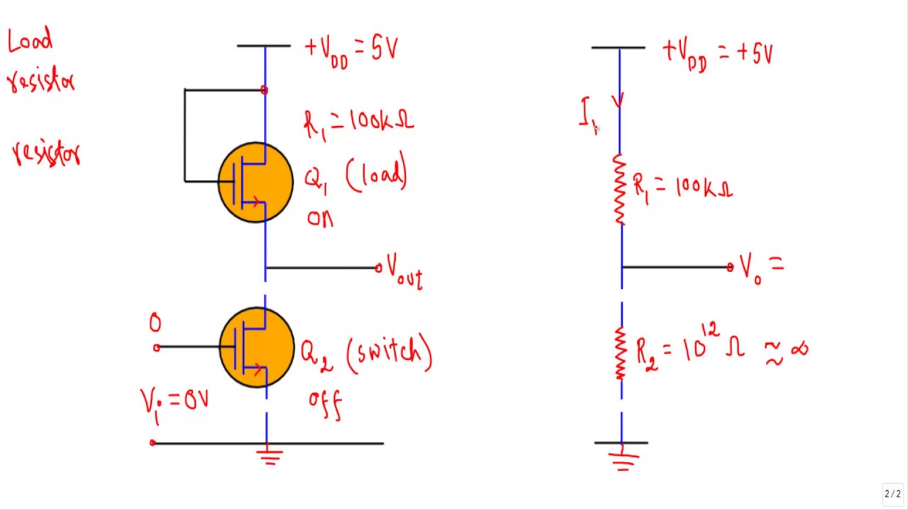
Logic inverter circuit. An inverter circuit outputs a voltage representing the opposite logic level to its input. Its main function is to invert the input signal applied. Multimedia logic digital circuit design simulator download. This multimedia logic simulator software is simplest most powerful most universal languages known digital logic.
A power inverter or inverter is an electronic device or circuitry that changes direct current dc to alternating current ac. The input voltage output voltage and frequency and overall power handling depend on the design of the specific device or circuitry. Principle behind this circuit. The basic idea behind every inverter circuit is to produce oscillations using the given dc and apply these oscillations across the primary of the transformer by amplifying the current.
Softstart uk ltd the uks 1 supplier of controlled starting and motor protection equipment offering soft starters up to 3000a and up to 15kv. How to build an inverter with a transistor. In this circuit we will build an inverter with a transistor. An inverter is a component or device that inverts the state or logic level of a signal to the opposite logic level.

Inverter Logic Gate Wikipedia

Logic Not Gate Tutorial With Logic Not Gate Truth Tablebasic

Transistor Logic Not Gate Inverter

Inverter Logic Gate Wikipedia

Logic Not Gate Tutorial With Logic Not Gate Truth Tablebasic

Inverter Logic Gate Wikipedia

The Not Gate Logic Gates Electronics Textbook

What Is Not Gate Inverter Not Logic Gate Inverter Circuit Using

Inverter Logic Gate Wikipedia

What Is Not Gate Inverter Not Logic Gate Inverter Circuit Using
Logic Not Gate Tutorial With Logic Not Gate Truth Tablebasic

Circuit Diagram Of An Integrated Injection Logic Inverter

Ecl Inverter Circuit Youtube

Digital Logic Why Does An Inverter Circuit Not Gate Need Both A

Transistors Learn Sparkfun Com

What Is Not Gate Inverter Not Logic Gate Inverter Circuit Using

Cmos Gate Circuitry Logic Gates Electronics Textbook

Nmos Logic And Pmos Logic Electrical4u

The Basics Of Emitter Coupled Logic

Not Gate Or Inverter Gate Electronics Tutorials

Digital Logic Uses Of Inverters In This Circuit Electrical

Ternary Logic Inverter Circuit Simulator
Logic Not Gate Tutorial With Logic Not Gate Truth Tablebasic

Activity Ttl Inverter And Nand Gate Analog Devices Wiki

Low Power Recomendation For A Digital Inverter Made Of Discrete
Inverter Logic Gate Youtube

Activity Ttl Inverter And Nand Gate Analog Devices Wiki

Cmos Logic Function Followed By Inverter With Speed Up Circuit
What Is The Working Principle Of Cmos Inverter Quora

5 4 Nmos And Pmos Logic Gates Introduction To Digital Systems

Inverter Logic Gate Wikipedia
Nmos Inverter Youtube

An Inverter Circuit Implemented With Dynamic Current Mode Logic

What Is Not Gate Inverter Not Logic Gate Inverter Circuit Using

Solved Nmos Inverter Logic Inverter Is One Of The Most B

Chapter 10 Digital Cmos Logic Circuits Ppt Video Online Download
The First Eleven Part 11 Page 4

Vlsi Design Mos Inverter

An Inverter Circuit Showing Proposed Logic Download Scientific Diagram

Transistors Learn Sparkfun Com

Digital Logic Can A Simple Diode And Resistor In Series Qualify As

How To Build An Inverter With A Transistor
Logic Not Gate Tutorial With Logic Not Gate Truth Tablebasic

Inverter Logic Gate Wikipedia

Logic Inverter By Use Nmos Docsity

Cmos Inverters

Transistor Digital Logic Gates Awesome Digital Logic Why Does An

Ttl Nand And And Gates Logic Gates

The Not Gate Logic Gates Electronics Textbook

Solved 100 M1 100pf Figure 1 Open Drain Logic Inverter C
